[PARTS LIST] [TOOLS LIST] [LED PATTERN] [CIRCUIT DIAGRAM] [STEP-BY-STEP]
STEP 1:
For this particular design, the LEDs will be top-mounted. This will require a series of precisely-placed holes to be drilled into the project box. In order to make sure these holes are evenly spaced, you’ll need to create a drilling template. This template will mark where each hole needs to be drilled.
(NOTE: This template is based on this specific project box and this specific LED pattern. If you choose to use a different style of project box, or a different layout for the LEDs, you will need to measure and design a new template from scratch.)
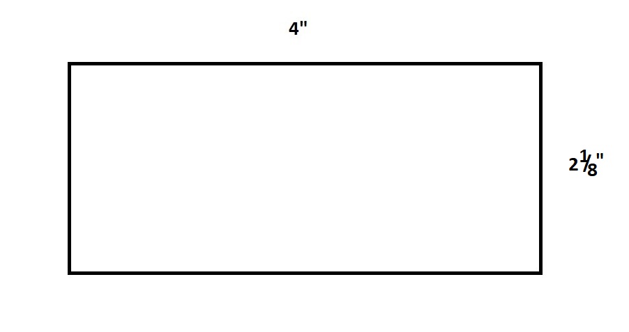
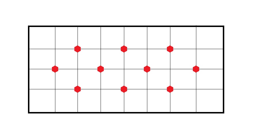
On a blank sheet of paper, draw a rectangle that is 4 inches long by 2 and 1/8 inches wide.
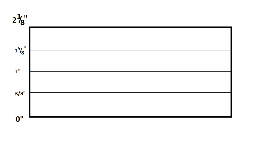
Inside this rectangle, measure and draw three, straight lines down the length of the rectangle.
Now measure and draw seven, straight lines across the width of the rectangle.
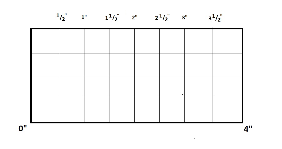
You now have a completed drilling template for your project box. You will need to drill your holes at each point on the grid signified by a red dot.
STEP 2:
Carefully cut this template from the rest of the paper and tape it to the top of the project box.
STEP 3:
Remove the back panel from the project box and set it aside, if you haven’t already. Carefully drill the holes for the LEDs. Be sure you are drilling straight down into the project box and not at an angle.
STEP 4:
Before we put the drill away, let’s drill a hole for the switch. The obvious options for where to place the switch is either on the back panel or on the side panel. My recommendation is to place it on the side panel. (You’ll see why this is the best spot once you get to Step 12.)
Measure out a spot that is dead-center on the side panel and drill the hole for the switch. Remember to drill straight down and not at an angle. Mount the switch in this hole.
STEP 5:
Now we’re going to glue the LEDs into the project box, and this is where a little attention to detail is really important. If you haven’t done so already, go ahead and print out the 10-LED (200mW) Infrared Light LED Pattern and keep it handy for easy reference during the duration of the gluing process.
Place the project box in front of you with the space allotted for the battery component to your right. On the 10-LED (200mW) Infrared Light LED Pattern diagram, you’ll see that every position has a negative (-) and positive (+) symbol. These symbols denote the positive and negative leads for each LED and how each LED should be oriented when mounted into the project box.
For instance, the LED in position 1 is mounted with its negative lead facing north and its positive lead facing south. The LED in position 2 has its negative lead facing east and its positive lead facing west. And, so on.
By mounting the LEDs in such a precise way, it’ll make the soldering process in Step 8 so much easier.
Using a toothpick or hobby paint brush, carefully coat the bottom of the LED with PVC glue. Insert the leads of the LED through the hole, making sure the positive and negative leads are oriented correctly, and press the LED to the surface of the project box. Apply steady pressure for about a minute. Repeat this process for the remaining nine LEDs.
Now, carefully flip the project box over and apply a generous drop of PVC glue to the underside of each LED.
Allow the glue to set for 24 hours.
STEP 6:
Create the positive wiring junction.
STEP 7:
Create the negative wiring junction.
STEP 8:
After allowing the glue to dry, and using needlenose pliers, carefully bend the leads of the LEDs so that they touch each other. DO NOT bend the following leads: 1+, 5-, 6+, and 10-. Carefully solder every point where LED leads touch.
STEP 9:
Attach the positive wiring junction.
STEP 10:
Attach the negative wiring junction.
STEP 11:
Attach a 9-volt battery and test the circuit.
STEP 12:
If everything works, run hot glue over every lead in the circuit, including the soldered connections of the positive and negative wiring junctions as well as the contact points of the switch. You want to make sure every exposed piece of wire and metal in the circuit is liberally coated in hot glue. Allow the hot glue to dry and harden.
I realize the thought of using hot glue on an electronic circuit seems like an odd, or even a cost-cutting approach, but this is actually more common than you might think, especially when it comes to DIY projects.
When hot glue is used to hold everything in place, rather than a circuit board, it’s often referred to as a floating circuit. The majority of infrared lights you’ll find being sold online make use of the same approach. Open them up and take a look for yourself. While circuit boards are the best option for mounting electronic components, keeping them securely in place so they don’t accidentally touch and short out, hot glue is an acceptable and time-saving alternative. Plus, hot glue has the added benefit of insulating the circuit and providing protection against moisture and corrosion.
Earlier, you had the choice of placing the switch either on the back panel or the side panel. After hot gluing the circuit, the recommendation I made about placing the switch on the side should seem obvious now. If the switch is placed on the back panel, it becomes difficult to screw the back panel on to the project box. The length of the switch, combined with the amount of dried hot glue on the circuit, creates a real challenge for screwing down the back panel and creating a tight seal.
STEP 13:
Attach the back cover of the project box. Make sure to allow for the 9-volt connector to hang out of the box’s battery compartment.
STEP 14:
Glue the tripod mount to the project box using the PVC glue. Allow the glue to set for 24 hours.
THAT’S IT! YOU’RE DONE!
The only thing this light is missing is some kind of diffuser. When you look at the two images below, the first one is a screenshot from video taken with a nightvision-capable handicam. The room is well-lit by the light and the light looks like it has a pretty good spread. But, if you look closely, you can see that the light is strong in the center and lessens as it nears the edges of the screenshot. There is a flashlight effect at play, and you can see it even more pronounced in the second screenshot.
The second screenshot is from a video taken with a nightvision-capable action camera. Action cameras use wide-angle lenses, which produce a fisheye effect in the video, and this makes the flashlight effect of the light much more noticeable. By adding a diffuser, which is generally just a clouded or frosted piece of plastic, it will reduce the flashlight effect and give the infrared light a more even spread across the room.
At this time, and because I do not have access to a 3-D printer, I still have not come up with a design for a diffuser. If you have any ideas, please don’t hesitate to share them in the comments below!
[PARTS LIST] [TOOLS LIST] [LED PATTERN] [CIRCUIT DIAGRAM] [STEP-BY-STEP]
